Butt Weld Pipe Fittings
Shenghe takes pride in providing high-quality butt weld pipe fittings to meet the demands of various industries. Our extensive range of butt weld pipe fittings is designed to ensure superior performance, exceptional durability, and precise fitment. Made from premium materials and manufactured with advanced techniques, our butt weld pipe fittings are engineered to withstand harsh operating conditions, maintain leak-free connections, and ensure long-term reliability.
If you’re looking for high-quality butt weld pipe fittings, contact us now for customized size and material grade design.
Get A Free Quote Now
Butt Weld Cap For Sale
Butt weld caps are essential components in piping systems, widely used to seal the end of pipes and provide a secure, leak-proof connection. These caps, also known as pipe caps or end caps, offer numerous benefits and are considered crucial in various industries.
Shenghe has butt weld caps available in various sizes, material grades and dimensions to accommodate different pipe diameters, allowing for flexibility in system design and installation.


Butt Weld Elbow For Sale
A butt weld elbow is a type of pipe fitting used to change the direction of flow in a piping system. It is designed with a curved or angled section, allowing for a smooth transition and redirection of the fluid or gas passing through the pipes.
Butt weld elbows are commonly used in industries such as oil and gas, petrochemical, chemical, power generation, water treatment, and many more. They are highly versatile and can be found in a wide range of applications, including pipelines, plumbing systems, and industrial processes.
These elbows come in various angles, with 90-degree and 45-degree elbows being the most common. However, they can also be manufactured in custom angles to suit specific project requirements. The choice of the angle depends on factors such as the layout of the piping system, space constraints, and the desired flow direction.


Butt Weld Reducer For Sale
A butt weld reducer is designed to connect pipes with different diameters, allowing for a smooth and seamless transition in the piping network. One of the key advantages of a butt weld reducer is its ability to eliminate the need for complex piping configurations or adapters. By providing a straightforward and efficient solution, it simplifies the installation process and ensures a secure and leak-free connection.
Shenghe butt weld reducer is commonly manufactured using high-quality materials such as stainless steel, carbon steel, or alloy steel, ensuring durability and resistance to corrosion even in demanding operating conditions.


Butt Weld Tee & Cross For Sale
Butt weld tee and cross play a crucial role in fluid distribution and control. These fittings are designed to join three or four pipes together at right angles, enabling the flow of liquids, gases, or slurries within a piping system.
We employ advanced welding techniques and use premium-grade materials to ensure strong and leak-free joints. Our fittings exhibit excellent dimensional accuracy, allowing for easy installation and seamless integration into various piping systems.
We offer customization options to tailor fittings to specific project needs, including different degrees of angles, wall thicknesses, and materials such as carbon steel, stainless steel, alloy steel, and more.


Lap Joint Stub End For Sale
A lap joint stub end is a type of pipe fitting used in piping systems to provide a leak-proof connection between pipes of different materials or sizes. It is designed to be welded onto the end of a pipe and provides a smooth transition to another flanged component, such as a flange or valve.
The lap joint stub end consists of two main components: the stub end itself and a lap joint flange. The stub end is a short piece of pipe with a plain or threaded end, while the lap joint flange has a flat face and a raised ring or collar on the inner side.
Lap joint stub ends are commonly used in applications where quick disassembly and reassembly of flanged connections are required, such as in piping systems that need frequent cleaning or inspection. They are also suitable for systems that have a combination of different pipe materials, as they enable easy transition between dissimilar materials.


Butt Weld Pipe Bend For Sale
A butt weld pipe bend is a commonly used pipe fitting that is designed to redirect the flow of fluids or gases in a piping system. It is a curved section of pipe that allows for smooth directional changes, eliminating the need for additional fittings or joints. This type of pipe bend is typically fabricated by welding two pipe ends together, forming a smooth and seamless curve.
At Shenghe, we specialize in manufacturing high-quality butt weld pipe bends that adhere to international standards and meet the specific needs of our customers. Our pipe bends undergo stringent quality control measures to ensure flawless fabrication and exceptional performance.


Butt Weld Pipe Fittings Standards
| ASME B16.9 | ASME B16.28 | ASME B16.49 | MSS SP43 | MSS SP75 |
Note:
MSS SP-43 only covers stainless steel buttweld fittings made for use with Schedule 5S and 10S pipe and Stub Ends suitable for use with Schedule 40S pipe, as defined in ASME B36.19. The dimensions and dimensional tolerances defined in MSS SP-43 are substantially the same as those in ASME B16.9 specifications from NPS 1/2 – NPS 24. Except with regard to the outside diameter at the bevel.
Butt Weld Pipe Fittings Material Grades
| Nickel Alloy | ASTM/ASME SB366 Alloy 200/UNS N02200, Alloy 800HT/Incoloy 800HT/UNS N08811, Alloy 400/Monel 400/UNS N04400, F904L/UNS N08904, Alloy 800/Incoloy 800/UNS N08800, Alloy C-2000/UNS N06200, Alloy 925/Incoloy 925/UNS N09925, Alloy C-22/UNS N06022, Alloy 201/UNS N02201, Alloy C-276/Hastelloy C-276/UNS N10276, Alloy 625/UNS N06625, Nimonic 80A/Nickel Alloy 80A/UNS N07080, Alloy K-500/Monel K-500, Alloy 20/UNS N08020, Alloy 800H/Incoloy 800H/UNS N08810,Alloy 600/Inconel 600/UNS N06600, Alloy 31/UNS N08031,Hastelloy C-276/UNS N10276, Alloy 825/Incoloy 825/UNS N08825,Alloy 20/N08020 |
| Duplex and Super Duplex Steel | ASTM/ASME SA 815 WPS31803, WPS32205, WPS32750, WPS32760, WPS32550 |
| Stainless Steel | ASTM/ASME WP 304, WP 304L, WP 304H, WP 304LN, WP 304N, ASTM/ASME WP 316, WP 316L, WP 316H, WP 316LN, WP 316N, WP 316Ti, ASTM/ASME WP 321, WP 321H ASTM/ASME WP 347, WP 347H |
Butt Weld Pipe Fittings Advantages
High Strength
Our welded connection provides increased strength and structural integrity, making them suitable for high-pressure and high-temperature applications.
Smooth Design
The smooth inner surface of our butt weld pipe fittings also minimizes flow resistance and pressure drop, optimizing the overall system efficiency and operation.
Safe Use
Shenghe butt weld pipe fittings offer excellent dimensional accuracy, ensuring a tight and secure connection, which reduces the risk of leaks or failures.
Butt Weld Pipe Fittings Price
Customer Testimonials
“Butt weld pipe fittings we received from Shenghe have been exceptional. The attention to detail and precision in their manufacturing is evident. Even after years of regular use, the fittings have maintained their durability and reliability.”
Samuel
Brazil
“The versatility of Shenghe BW pipe fittings has made them a convenient solution for our diverse plumbing needs. Whether it is connecting pipes of different sizes, changing directions, or branching off into multiple lines, these fittings have provided seamless connectivity and flexibility.”
Chibesa Joseph
UAE
Butt Weld Pipe Fitting Dimensions
BW Elbows 45°-90° LR and 3D ASME B16.9:

| NPS | O.D.D | 90° LRA | 45° LRB | 90° 3DA | 45° 3DB |
| 1/2 | 21.3 | 38 | 16 | ||
| 3/4 | 26.7 | 38 | 19 | 57 | 24 |
| 1 | 33.4 | 38 | 22 | 76 | 31 |
| 1.1/4 | 42.2 | 48 | 25 | 95 | 39 |
| 1.1/2 | 48.3 | 57 | 29 | 114 | 47 |
| 2 | 60.3 | 76 | 35 | 152 | 63 |
| 2.1/2 | 73 | 95 | 44 | 190 | 79 |
| 3 | 88.9 | 114 | 51 | 229 | 95 |
| 3.1/2 | 101.6 | 133 | 57 | 267 | 111 |
| 4 | 114.3 | 152 | 64 | 305 | 127 |
| 5 | 141.3 | 190 | 79 | 381 | 157 |
| 6 | 168.3 | 229 | 95 | 457 | 189 |
| 8 | 219.1 | 305 | 127 | 610 | 252 |
| 10 | 273 | 381 | 159 | 762 | 316 |
| 12 | 323.8 | 457 | 190 | 914 | 378 |
| 14 | 355.6 | 533 | 222 | 1067 | 441 |
| 16 | 406.4 | 610 | 254 | 1219 | 505 |
| 18 | 457 | 686 | 286 | 1372 | 568 |
| 20 | 508 | 762 | 318 | 1524 | 632 |
| 22 | 559 | 838 | 343 | 1676 | 694 |
| 24 | 610 | 914 | 381 | 1829 | 757 |
| 26 | 660 | 991 | 406 | 1981 | 821 |
| 28 | 711 | 1067 | 438 | 2134 | 883 |
| 30 | 762 | 1143 | 470 | 2286 | 946 |
| 32 | 813 | 1219 | 502 | 2438 | 1010 |
| 34 | 864 | 1295 | 533 | 2591 | 1073 |
| 36 | 914 | 1372 | 565 | 2743 | 1135 |
| 38 | 965 | 1448 | 600 | 2896 | 1200 |
| 40 | 1016 | 1524 | 632 | 3048 | 1264 |
| 42 | 1067 | 1600 | 660 | 3200 | 1326 |
| 44 | 1118 | 1676 | 695 | 3353 | 1389 |
| 46 | 1168 | 1753 | 727 | 3505 | 1453 |
| 48 | 1219 | 1829 | 759 | 3658 | 1516 |
Notes:
Dimensions are in millimeters unless otherwise indicated.
Wall thickness (t) must be specified by customer. A & B are Center to End dimensions
Dimensional Tolerances of Butt Weld Elbows
| Nominal Pipe Size | 1/2 to 2.1/2 | 3 to 3.1/2 | 4 | 5 to 8 | |
| Outside Diameter at Bevel (D) | + 1.6 – 0.8 | 1.6 | 1.6 | + 2.4 – 1.6 | |
| Inside Diameter at End | 0.8 | 1.6 | 1.6 | 1.6 | |
| Center to End LR (A/B) | 2 | 2 | 2 | 2 | |
| Center to End 3D (A/B) | 3 | 3 | 3 | 3 | |
| Nominal Pipe Size | 10 to 18 | 20 to 24 | 26 to 30 | 32 to 48 | |
| Outside Diameter at Bevel (D) | + 4 – 3.2 | + 6.4 – 4.8 | + 6.4 – 4.8 | + 6.4 – 4.8 | |
| Inside Diameter at End | 3.2 | 4.8 | + 6.4 – 4.8 | + 6.4 – 4.8 | |
| Center to End LR (A/B) | 2 | 2 | 3 | 5 | |
| Center to End 3D (A/B) | 3 | 3 | 6 | 6 | |
| Wall Thickness (t) | Not less than 87.5% of Nominal Wall Thickness | ||||
Note: Dimensional tolerances are in millimeters unless otherwise indicated and are equal ± except as noted.
Butt Weld Caps ASME B16.9:

| NPS | O.D.D | LengthH | LengthH(1) |
| 1/2 | 21.3 | 25 | 25 |
| 3/4 | 26.7 | 25 | 25 |
| 1 | 33.4 | 38 | 38 |
| 1.1/4 | 42.2 | 38 | 38 |
| 1.1/2 | 48.3 | 38 | 38 |
| 2 | 60.3 | 38 | 44 |
| 2.1/2 | 73 | 38 | 51 |
| 3 | 88.9 | 51 | 64 |
| 3.1/2 | 101.6 | 64 | 76 |
| 4 | 114.3 | 64 | 76 |
| 5 | 141.3 | 76 | 89 |
| 6 | 168.3 | 89 | 102 |
| 8 | 219.1 | 102 | 127 |
| 10 | 273 | 127 | 152 |
| 12 | 323.8 | 152 | 178 |
| 14 | 355.6 | 165 | 191 |
| 16 | 406.4 | 178 | 203 |
| 18 | 457 | 203 | 229 |
| 20 | 508 | 229 | 254 |
| 22 | 559 | 254 | 254 |
| 24 | 610 | 267 | 305 |
| 26 | 660 | 267 | – |
| 28 | 711 | 267 | – |
| 30 | 762 | 267 | – |
| 32 | 813 | 267 | – |
| 34 | 864 | 237 | – |
| 36 | 914 | 267 | – |
| 38 | 965 | 305 | – |
| 40 | 1016 | 305 | – |
| 42 | 1067 | 305 | – |
| 44 | 1118 | 343 | – |
| 46 | 1168 | 343 | – |
| 48 | 1219 | 343 | – |
Notes:
Dimensions are in millimeters unless otherwise indicated.
Wall thickness (t) must be specified by customer.
The shape shall be ellipsoidal and shall conform to the requirements given in the ASME Boiler and Pressure Vessel Code.
Length (H) applies for thickness not exceeding that given in column “Wall Thickness” for Length, H.
Length (H1) applies for thickness greater than that given in column “Wall Thickness” for NPS 24 and smaller. For NPS 26 and larger, length H1 shall be by agreement between the manufacturer and purchaser.
Dimensional Tolerances of End Caps ASME B16.9
| Nominal Pipe Size | 1/2 to 2.1/2 | 3 to 3.1/2 | 4 | 5 to 8 | |
| Outside Diameter at Bevel (D) | + 1.6 – 0.8 | 1.6 | 1.6 | + 2.4 – 1.6 | |
| Inside Diameter at End | 0.8 | 1.6 | 1.6 | 1.6 | |
| Overall Length (H) | 3 | 3 | 3 | 6 | |
| Nominal Pipe Size | 10 to 18 | 20 to 24 | 26 to 30 | 32 to 48 | |
| Outside Diameter at Bevel (D) | + 4 – 3.2 | + 6.4 – 4.8 | + 6.4 – 4.8 | + 6.4 – 4.8 | |
| Inside Diameter at End | 3.2 | 4.8 | + 6.4 – 4.8 | + 6.4 – 4.8 | |
| Overall Length (H) | 6 | 6 | 10 | 10 | |
| Wall Thickness (t) | Not less than 87.5% of Nominal Wall Thickness | ||||
Note: Dimensional tolerances are in millimeters unless otherwise indicated and are equal ± except as noted.
Butt Weld Reducers Concentric and Eccentric ASME B16.9:

| NPS | O.D.D | O.D.D1 | LengthH |
| 3/4 – 1/2 | 26.7 | 21.3 | 38 |
| 1 – 1/2 | 33.4 | 21.3 | 51 |
| 1 – 3/4 | 33.4 | 26.7 | 51 |
| 1.1/4 – 1/2 | 42.2 | 21.3 | 51 |
| 1.1/4 – 3/4 | 42.2 | 26.7 | 51 |
| 1.1/4 – 1 | 42.2 | 33.4 | 51 |
| 1.1/2 – 1/2 | 48.3 | 21.3 | 64 |
| 1.1/2 – 3/4 | 48.3 | 26.7 | 64 |
| 1.1/2 – 1 | 48.3 | 33.4 | 64 |
| 1.1/2 – 1.1/4 | 48.3 | 42.2 | 64 |
| 2 – 3/4 | 60.3 | 26.7 | 76 |
| 2 – 1 | 60.3 | 33.4 | 76 |
| 2 – 1.1/4 | 60.3 | 42.2 | 76 |
| 2 – 1.1/2 | 60.3 | 48.3 | 76 |
| 2.1/2 – 1 | 73 | 33.4 | 89 |
| 2.1/2 – 1.1/4 | 73 | 42.2 | 89 |
| 2.1/2 – 1.1/2 | 73 | 48.3 | 89 |
| 2.1/2 – 2 | 73 | 60.3 | 89 |
| 3 – 1.1/4 | 88.9 | 42.2 | 89 |
| 3 – 1.1/2 | 88.9 | 48.3 | 89 |
| 3 – 2 | 88.9 | 60.3 | 89 |
| 3 – 2.1/2 | 88.9 | 73 | 89 |
| 3.1/2 – 1.1/4 | 101.6 | 42.2 | 102 |
| 3.1/2 – 1.1/2 | 101.6 | 48.3 | 102 |
| 3.1/2 – 2 | 101.6 | 60.3 | 102 |
| 3.1/2 – 2.1/2 | 101.6 | 73 | 102 |
| 3.1/2 – 3 | 101.6 | 88.9 | 102 |
| 4 – 1.1/2 | 114.3 | 48.3 | 102 |
| 4 – 2 | 114.3 | 60.3 | 102 |
| 4 – 2.1/2 | 114.3 | 73 | 102 |
| 4 – 3 | 114.3 | 88.9 | 102 |
| 4 – 3.1/2 | 114.3 | 101.6 | 102 |
| 5 – 2 | 141.3 | 60.3 | 127 |
| 5 – 2.1/2 | 141.3 | 73 | 127 |
| 5 – 3 | 141.3 | 88.9 | 127 |
| 5 – 3.1/2 | 141.3 | 101.6 | 127 |
| 5 – 4 | 141.3 | 114.3 | 127 |
| 6 – 2.1/2 | 168.3 | 73 | 140 |
| 6 – 3 | 168.3 | 88.9 | 140 |
| 6 – 3.1/2 | 168.3 | 101.6 | 140 |
| 6 – 4 | 168.3 | 114.3 | 140 |
| 6 – 5 | 168.3 | 141.3 | 140 |
| 8 – 3.1/2 | 219.1 | 101.6 | 152 |
| 8 – 4 | 219.1 | 114.3 | 152 |
| 8 – 5 | 219.1 | 141.3 | 152 |
| 8 – 6 | 219.1 | 168.3 | 152 |
| 10 – 4 | 273 | 114.3 | 178 |
| 10 – 5 | 273 | 141.3 | 178 |
| 10 – 6 | 273 | 168.3 | 178 |
| 10 – 8 | 273 | 219.1 | 178 |
| 12 – 5 | 323.9 | 141.3 | 203 |
| 12 – 6 | 323.9 | 168.3 | 203 |
| 12 – 8 | 323.9 | 219.1 | 203 |
| 12 – 10 | 323.9 | 273 | 203 |
| 14 – 6 | 355.6 | 168.3 | 330 |
| 14 – 8 | 355.6 | 219.1 | 330 |
| 14 – 10 | 355.6 | 273 | 330 |
| 14 – 12 | 355.6 | 323.9 | 330 |
| 16 – 8 | 406.4 | 219 | 356 |
| 16 – 10 | 406.4 | 273 | 356 |
| 16 – 12 | 406.4 | 323.9 | 356 |
| 16 – 14 | 406.4 | 355.6 | 356 |
| 18 – 10 | 457 | 273 | 381 |
| 18 – 12 | 457 | 323.9 | 381 |
| 18 – 14 | 457 | 355.6 | 381 |
| 18 – 16 | 457 | 406.4 | 381 |
| 20 – 12 | 508 | 323.9 | 508 |
| 20 – 14 | 508 | 355.6 | 508 |
| 20 – 16 | 508 | 406.4 | 508 |
| 20 – 18 | 508 | 457 | 508 |
| 22 – 14 | 559 | 355.6 | 508 |
| 22 – 16 | 559 | 406.4 | 508 |
| 22 – 18 | 559 | 457 | 508 |
| 22 – 20 | 559 | 508 | 508 |
| 24 – 16 | 610 | 406.4 | 508 |
| 24 – 18 | 610 | 457 | 508 |
| 24 – 20 | 610 | 508 | 508 |
| 24 – 22 | 610 | 559 | 508 |
| 26 – 18 | 660 | 457 | 610 |
| 26 – 20 | 660 | 508 | 610 |
| 26 – 22 | 660 | 559 | 610 |
| 26 – 24 | 660 | 610 | 610 |
| 28 – 18 | 711 | 457 | 610 |
| 28 – 20 | 711 | 508 | 610 |
| 28 – 24 | 711 | 610 | 610 |
| 28 – 26 | 711 | 660 | 610 |
| 30 – 20 | 762 | 508 | 610 |
| 30 – 24 | 762 | 610 | 610 |
| 30 – 26 | 762 | 660 | 610 |
| 30 – 28 | 762 | 711 | 610 |
| 32 – 24 | 813 | 610 | 610 |
| 32 – 26 | 813 | 660 | 610 |
| 32 – 28 | 813 | 711 | 610 |
| 32 – 30 | 813 | 762 | 610 |
| 34 – 24 | 864 | 610 | 610 |
| 34 – 26 | 864 | 660 | 610 |
| 34 – 30 | 864 | 762 | 610 |
| 34 – 32 | 864 | 813 | 610 |
| 36 – 24 | 914 | 610 | 610 |
| 36 – 26 | 914 | 660 | 610 |
| 36 – 30 | 914 | 762 | 610 |
| 36 – 32 | 914 | 813 | 610 |
| 36 – 34 | 914 | 864 | 610 |
| 38 – 26 | 965 | 660 | 610 |
| 38 – 28 | 965 | 711 | 610 |
| 38 – 30 | 965 | 762 | 610 |
| 38 – 32 | 965 | 813 | 610 |
| 38 – 34 | 965 | 864 | 610 |
| 38 – 36 | 965 | 914 | 610 |
| 40 – 30 | 1016 | 762 | 610 |
| 40 – 32 | 1016 | 813 | 610 |
| 40 – 34 | 1016 | 864 | 610 |
| 40 – 36 | 1016 | 914 | 610 |
| 40 – 38 | 1016 | 965 | 610 |
Notes: Dimensions are in millimeters unless otherwise indicated. Wall thickness (t) must be specified by customer.
Dimensional Tolerances of Concentric and Eccentric Reducers ASME B16.9
| Nominal Pipe Size | 1/2 to 2.1/2 | 3 to 3.1/2 | 4 | 5 to 8 | |
| Outside Diameter at Bevel (D) | + 1.6 – 0.8 | 1.6 | 1.6 | + 2.4 – 1.6 | |
| Inside Diameter at End | 0.8 | 1.6 | 1.6 | 1.6 | |
| Overall Length (H) | 2 | 2 | 2 | 2 | |
| Nominal Pipe Size | 10 to 18 | 20 to 24 | 26 to 30 | 32 to 48 | |
| Outside Diameter at Bevel (D) | + 4 – 3.2 | + 6.4 – 4.8 | + 6.4 – 4.8 | + 6.4 – 4.8 | |
| Inside Diameter at End | 3.2 | 4.8 | + 6.4 – 4.8 | + 6.4 – 4.8 | |
| Overall Length (H) | 2 | 2 | 5 | 5 | |
| Wall Thickness (t) | Not less than 87.5% of Nominal Wall Thickness | ||||
Note: Dimensional tolerances are in millimeters unless otherwise indicated and are equal ± except as noted.
Butt Weld Straight Tees ASME B16.9:

| NPS | O.D.D | Center to EndC | Center to EndM |
| 1/2 | 21.3 | 25 | 25 |
| 3/4 | 26.7 | 29 | 29 |
| 1 | 33.4 | 38 | 38 |
| 1.1/4 | 42.2 | 48 | 48 |
| 1.1/2 | 48.3 | 57 | 57 |
| 2 | 60.3 | 64 | 64 |
| 2.1/2 | 73 | 76 | 76 |
| 3 | 88.9 | 86 | 86 |
| 3.1/2 | 101.6 | 95 | 95 |
| 4 | 114.3 | 105 | 105 |
| 5 | 141.3 | 124 | 124 |
| 6 | 168.3 | 143 | 143 |
| 8 | 219.1 | 178 | 178 |
| 10 | 273 | 216 | 216 |
| 12 | 323.8 | 254 | 254 |
| 14 | 355.6 | 279 | 279 |
| 16 | 406.4 | 305 | 305 |
| 18 | 457 | 343 | 343 |
| 20 | 508 | 381 | 381 |
| 22 | 559 | 419 | 419 |
| 24 | 610 | 432 | 432 |
| 26 | 660 | 495 | 495 |
| 28 | 711 | 521 | 521 |
| 30 | 762 | 559 | 559 |
| 32 | 813 | 597 | 597 |
| 34 | 864 | 635 | 635 |
| 36 | 914 | 673 | 673 |
| 38 | 965 | 711 | 711 |
| 40 | 1016 | 749 | 749 |
| 42 | 1067 | 762 | 711 |
| 44 | 1118 | 813 | 762 |
| 46 | 1168 | 851 | 800 |
| 48 | 1219 | 889 | 838 |
Notes:
Dimensions are in millimeters unless otherwise indicated.
Wall thickness (t) must be specified by customer.
Outlet dimension (M) for NPS 26 and larger is recommended but not required.
Dimensional Tolerances Straight Tees ASME B16.9
| Nominal Pipe Size | 1/2to2.1/2 | 3to3.1/2 | 4 | 5to8 | 10to18 | 20to24 | 26to30 | 32to48 | |
| Outside Diaat Bevel (D) | +1.6 -0.8 | 1.6 | 1.6 | +2.4 -1.6 | +4 -3.2 | +6.4 -4.8 | +6.4 -4.8 | +6.4 -4.8 | |
| Inside Dia at End | 0.8 | 1.6 | 1.6 | 1.6 | 3.2 | 4.8 | +6.4 -4.8 | +6.4 -4.8 | |
| Center to End (C / M) | 2 | 2 | 2 | 2 | 2 | 2 | 3 | 5 | |
| Wall Thk (t) | Not less than 87.5% of Nominal Wall Thickness | ||||||||
Note: Dimensional tolerances are in millimeters unless otherwise indicated and are equal ± except as noted.
Lap Joint Stub Ends Schedule STD XS ASME B16.9:

Schedule STD:
| NPS | OD | T | G | F | R | kg |
| 1/2 | 21.3 | 2.77 | 34.9 | 76.2 | 3.18 | 0.16 |
| 3/4 | 26.7 | 2.87 | 42.9 | 76.2 | 3.18 | 0.23 |
| 1 | 33.4 | 3.38 | 50.8 | 101.6 | 3.18 | 0.29 |
| 1.1/4 | 42.2 | 3.56 | 63.5 | 101.6 | 4.76 | 0.45 |
| 1.1/2 | 48.3 | 3.68 | 73 | 101.6 | 6.35 | 0.54 |
| 2 | 60.3 | 3.91 | 92.1 | 152.4 | 7.94 | 1 |
| 2.1/2 | 73 | 5.16 | 104.8 | 152.4 | 7.94 | 1.5 |
| 3 | 88.9 | 5.49 | 127 | 152.4 | 9.53 | 2.1 |
| 3.1/2 | 101.6 | 5.74 | 139.7 | 152.4 | 9.53 | 2.5 |
| 4 | 114.3 | 6.02 | 157.2 | 152.4 | 11.11 | 3 |
| 5 | 141.3 | 6.55 | 185.7 | 203.2 | 11.11 | 5.4 |
| 6 | 168.3 | 7.11 | 215.9 | 203.2 | 12.70 | 7.3 |
| 8 | 219.1 | 8.18 | 269.9 | 203.2 | 12.70 | 11.6 |
| 10 | 273.1 | 9.27 | 323.9 | 254 | 12.70 | 18 |
| 12 | 323.9 | 9.53 | 381 | 254 | 12.70 | 21 |
| 14 | 355.6 | 9.53 | 412.8 | 304.8 | 12.70 | 28 |
| 16 | 406.4 | 9.53 | 469.9 | 304.8 | 12.70 | 34 |
| 18 | 457.2 | 9.53 | 533.4 | 304.8 | 12.70 | 39 |
| 20 | 508 | 9.53 | 584.2 | 304.8 | 12.70 | 44 |
| 24 | 609.6 | 9.53 | 692.2 | 304.8 | 12.70 | 57 |
Notes: Dimensions are in millimeters unless otherwise indicated. Weights are in kilograms and approximately given.
Schedule XS:
| NPS | OD | T | G | F | R | kg |
| 1/2 | 21.3 | 3.73 | 34.9 | 76.2 | 3.18 | 0.2 |
| 3/4 | 26.7 | 3.91 | 42.9 | 76.2 | 3.18 | 0.3 |
| 1 | 33.4 | 4.55 | 50.8 | 101.6 | 3.18 | 0.4 |
| 1.1/4 | 42.2 | 4.85 | 63.5 | 101.6 | 4.76 | 0.6 |
| 1.1/2 | 48.3 | 5.08 | 73 | 101.6 | 6.35 | 0.7 |
| 2 | 60.3 | 5.54 | 92.1 | 152.4 | 7.94 | 1.4 |
| 2.1/2 | 73 | 7.01 | 104.8 | 152.4 | 7.94 | 2 |
| 3 | 88.9 | 7.62 | 127 | 152.4 | 9.53 | 2.9 |
| 3.1/2 | 101.6 | 8.08 | 139.7 | 152.4 | 9.53 | 3.4 |
| 4 | 114.3 | 8.56 | 157.2 | 152.4 | 11.11 | 4.1 |
| 5 | 141.3 | 9.53 | 185.7 | 203.2 | 11.11 | 7.5 |
| 6 | 168.3 | 10.97 | 215.9 | 203.2 | 12.70 | 10 |
| 8 | 219.1 | 12.70 | 269.9 | 203.2 | 12.70 | 16 |
| 10 | 273.1 | 12.70 | 323.9 | 254 | 12.70 | 24 |
| 12 | 323.9 | 12.70 | 381 | 254 | 12.70 | 29 |
| 14 | 355.6 | 12.70 | 412.8 | 304.8 | 12.70 | 38 |
| 16 | 406.4 | 12.70 | 469.9 | 304.8 | 12.70 | 43 |
| 18 | 457.2 | 12.70 | 533.4 | 304.8 | 12.70 | 49 |
| 20 | 508 | 12.70 | 584.2 | 304.8 | 12.70 | 63 |
| 24 | 609.6 | 12.70 | 692.2 | 304.8 | 12.70 | 76 |
Note: Dimensions are in millimeters unless otherwise indicated. Weights are in kilograms and approximately given.
Dimensional Tolerances of Stub Ends ASME B16.9
| Nominal Pipe Size | 1/2 to 2.1/2 | 3 to 3.1/2 | 4 | 5 to 8 | 10 to 18 | 20 to 24 |
| Outside Diameter at Welding End (OD) | + 1.6 – 0.8 | 1.6 | 1.6 | + 2.29 – 1.6 | + 4.06 – 3.05 | + 6.35 – 4.83 |
| Overall Length (F) | 1.6 | 1.6 | 1.6 | 1.6 | 2 | 2 |
| Outside Diameter of Lap (G) | + 0 – 0.76 | + 0 – 0.76 | + 0 – 0.76 | + 0 – 0.76 | + 0 – 1.6 | + 0 – 1.6 |
| Thickness of Lap (T) | + 1.52 – 0 | + 1.52 – 0 | + 1.52 – 0 | + 1.52 – 0 | + 1.52 – 0 | + 1.52 – 0 |
| Fillet Radius of Lap (R) | + 0 – 0.76 | + 0 – 0.76 | + 0 – 1.6 | + 0 – 1.6 | + 0 – 1.6 | + 0 – 1.6 |
| Wall Thickness (t) | Not less than 87.5% of Nominal Wall Thickness | |||||
Note: Dimensional tolerances are in millimeters unless otherwise indicated.
Dimensions Butt Welded Stub Ends schedule 10S MSS SP-43 type A/B
| NPS | OD | T | G | F | RType A | RType B |
| 1/2 | 21.3 | 2.11 | 34.9 | 50.8 | 3.05 | 0.76 |
| 3/4 | 26.7 | 2.11 | 42.9 | 50.8 | 3.05 | 0.76 |
| 1 | 33.4 | 2.77 | 50.8 | 50.8 | 3.05 | 0.76 |
| 1.1/4 | 42.2 | 2.77 | 63.5 | 50.8 | 4.83 | 0.76 |
| 1.1/2 | 48.3 | 2.77 | 73 | 50.8 | 6.35 | 0.76 |
| 2 | 60.3 | 2.77 | 92.1 | 63.5 | 7.87 | 0.76 |
| 2.1/2 | 73 | 3.05 | 104.8 | 63.5 | 7.87 | 0.76 |
| 3 | 88.9 | 3.05 | 127 | 63.5 | 9.65 | 0.76 |
| 3.1/2 | 101.6 | 3.05 | 139.7 | 76.2 | 9.65 | 0.76 |
| 4 | 114.3 | 3.05 | 157.2 | 76.2 | 11.18 | 0.76 |
| 5 | 141.3 | 3.40 | 185.7 | 76.2 | 11.18 | 1.52 |
| 6 | 168.3 | 3.40 | 215.9 | 88.9 | 12.7 | 1.52 |
| 8 | 219.1 | 3.76 | 269.9 | 101.6 | 12.7 | 1.52 |
| 10 | 273.1 | 4.19 | 323.9 | 127 | 12.7 | 1.52 |
| 12 | 323.9 | 4.57 | 381 | 152.4 | 12.7 | 1.52 |
| 14 | 355.6 | 4.78 | 412.8 | 152.4 | 12.70 | 1.52 |
| 16 | 406.4 | 4.78 | 469.9 | 152.4 | 12.7 | 1.52 |
| 18 | 457.2 | 4.78 | 533.4 | 152.4 | 12.70 | 1.52 |
| 20 | 508 | 5.54 | 584.2 | 152.4 | 12.70 | 1.52 |
| 24 | 609.6 | 6.35 | 692.2 | 152.4 | 12.7 | 1.52 |
Note: Dimensions are in millimeters unless otherwise indicated. Weights are in kilograms and approximately given.
Dimensional Tolerances Stub Ends MSS SP-43

| Nominal Pipe Size | 1/2 to 2.1/2 | 3 to 3.1/2 | 4 | 5 to 8 | 10 to 18 | 20 to 24 |
| Outside Diameter at Welding End (OD) | 0.8 | 0.8 | 0.8 | + 1.6 – 0.8 | + 2.29 – 0.76 | + 3.05 – 0.76 |
| Overall Length (F) | 1.6 | 1.6 | 1.6 | 1.6 | 2 | 2 |
| Outside Diameter of Lap (G) | + 0 – 0.76 | + 0 – 0.76 | + 0 – 0.76 | + 0 – 0.76 | + 0 – 1.6 | + 0 – 1.6 |
| Thickness of Lap (T) | + 1.52 – 0 | + 1.52 – 0 | + 1.52 – 0 | + 1.52 – 0 | + 1.52 – 0 | + 1.52 – 0 |
| Fillet Radius of Lap (R) | + 0 – 0.76 | + 0 – 0.76 | + 0 – 1.6 | + 0 – 1.6 | + 0 – 1.6 | + 0 – 1.6 |
| Wall Thickness (t) | Not less than 87.5% of Nominal Wall Thickness | |||||
Notes: Dimensional tolerances are in millimeters unless otherwise indicated.
Shenghe BW Pipe Fittings Production Process

Shenghe is a renowned leader in the manufacturing of piping products, particularly specializing in butt weld pipe fittings in China. The production process of butt weld pipe fittings involves several key steps to ensure the creation of high-quality, durable products.
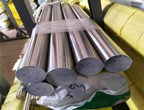
Firstly, the manufacturing process starts with the selection of premium quality raw materials, such as stainless steel, carbon steel, or alloy steel. These materials undergo rigorous quality checks to ensure that they meet the required standards and specifications.
Next, the raw materials are shaped and formed through processes such as forging or cold forming to achieve the desired dimensions and shapes of the butt weld pipe fittings. Precision is crucial to ensure that the fittings meet the precise requirements for installation and functionality.
Following this, the fittings undergo heat treatment to enhance their mechanical properties, such as strength and durability. This step is vital in ensuring that the fittings can withstand the extreme conditions and pressures to which they may be subjected during use.
Subsequently, the fittings are machined and finished to achieve the necessary surface smoothness and dimensional accuracy. This process is critical for ensuring leak-tight connections and optimal performance when integrated into piping systems.
Finally, the finished butt weld pipe fittings undergo thorough quality inspections to guarantee that they conform to international standards and customer specifications. This includes testing for dimensional accuracy, strength, and integrity of welds.
Get Your Free Quote Now.
Always Provides Customized Plan at Best Price
When you choose Shenghe, you’re guaranteed more than just off-the-shelf products. We believe in the power of customization, and our highly skilled engineers work closely with our clients to understand your project specifications, budget constraints, and timeline. This collaborative approach allows us to develop comprehensive and personalized plans that address all aspects of the project, from design and material selection to product functionality and installation.
Our dedicated sales team is ready to assist you by providing accurate and personalized quotations that cater to your project’s needs. Simply reach out to us, and our team will be delighted to discuss your requirements and provide you with a competitive quote.